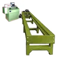
Horizontal CR 5
Product Details:
- Usage Industrial
- Color Green
- Product Type Other Testing Machines
- Click to View more
Test methods
- Tensile Test
- Compression Test
- Bend Test
- Single Shear
- Double Shear
- Proof Test [Stress Vs %Strain (If Extensometer is used)]
Test load
- 24-1200
- 30-1500
- 40-2000
Standards
- BS-1610:Part1:1992
- IS-1828:Part1:1991
Features :
The HorizontalTensile Chain and Rope Testing Machine incorporate design features to enable high accuracy testing with economy, speed, and versatility.
- Loading accuracy as high +/- 1 % as per Grade A of materials
- Fully customized Windows-based software for real-time graph & data processing with a wide range of data entry
- Motor-driven gear shaft for quick and effortless adjustment of test length to facilitate rapid fixing of test specimen High reading accuracy due to large size of the dial
- Wide range of standard and special accessories, including load stabilizer
- Large effective bed clearance enables testing of a wide range of specimens
- Simple controls for ease of operation
- Robust straining frame of an extremely rigid construction
- Safe operation ensured by means of safe devices
- Fully automatic load & displacement digital panel
Applications
Horizontal Chain and Rope Tensile Testing Machine is designed to test chains and ropes under tension.
Principle of Operation:
Operation of the machine is by hydraulic transmission of load from the test specimen to a separately housed load indicator. The hydraulic system is ideal since it replaces transmission of load through levers and knife-edges, which are prone to wear and damage due to shock on the rupture of test pieces.
Load is applied by the hydrostatically lubricated piston. Main cylinder pressure is transmitted to the pressure cell housed in the control panel. The pressure transmitted to the pressure cell is directly convert pressure into load in kN shows absolute load applied on the test specimen digitally.
Rotary encoder is used to show displacement & it will display with load in the electronic panel.
Machine consists of
- Straining UnitIt consists of a hydraulic cylinder and a crosshead coupled to the piston rod of the hydraulic cylinder, mounted on to a robust base. The cylinder and the piston are individually lapped to eliminate friction. The crosshead is connected to two screwed columns and is driven by a motor for rapid adjustment of test length.The stationary crosshead is pinned to the loading frame. It can be pinned along the bed length in steps of 500 mm. All these crossheads are on wheels to reduce friction while in motion.
An elongation scale with a minimum of 1 mm is provided to measure the elongation of the specimen.
- Control Panel The control panel consists of a power pack complete with drive motor and an oil tank, control valve, Pressure Transducer, Rotary Encoder, Digital indicator system.
- A) Power PackThe unit generates a maximum pressure of 200 kgf/cm2. The hydraulic pump provides continuously non-pulsating oil flow. Hence the load application is very smooth.
- B) Hydraulics Controls:Hand operated wheels are used to control flow to and from the hydraulic cylinder. The regulation of the oil is infinitely variable. Incorporated in the hydraulic system is a regulating valve. Which maintains a practically constant rate of crosshead movement.
- C) Load Displacement Indicator System:This is a microprocessor-based electronic panel which shows load & displacement digitally. It transfers all data to computer software with showing a real-time graph on our software…
A overload trip switch is incorporated which automatically. Cuts out the pump motor when the load range in use in exceeded.
Accuracy and Calibration:
All Horizontal Tensile Chain and Rope Testing Machines are closely controlled for sensitivity accuracy and calibration during every stage of manufacture. Every Machine is than calibrated over of its chart ranges in accordance with the procedure laid down in British Standards 1610-1964 and IS: 1828-1975.
Horizontal Chain and Rope Tensile Testing Machine comply with Grade “A” of BS: 1610-1964 and Grade 0.1 of IS: 1828-1975. An accuracy of + 1% is guaranteed from 20% of the load range selected to full load.
Special Accessories:
| Model | ME-TNE-SD 5 | ME-TNE-SD 10 | ME-TNE-SD 15 | ME-TNE-SD 20 | ME-TNE-SD 25 | ME-TNE-SD 50 | ME-TNE-SD 100 | |
| Maximum Capacity | 5 kN | 10 kN | 15 kN | 20 kN | 25 kN | 50 kN | 100 kN | |
| Power Supply | 230V AC / 50 Hz Single Phase | 415V AC / 50 Hz 3 Phase | ||||||
| Load Measurement | Using Strain Gauge Type Load Cells | |||||||
| Measuring Range & Accuracy | ±1% of the indicated load from 2% to 100% of Load Capacity | |||||||
| Distance Between Columns | 400 mm | |||||||
| Maximum Crosshead Stroke | 1000 mm without Load Cell & Grips | |||||||
| 230V AC / 50 Hz Single Phase | 415V AC / 50 Hz Three Phase | |||||||
| Test Speed | 0.01 to 250 mm/min || 0.5 to 500 mm/min || As per Requirement | |||||||
| Standard Accessories | Wedge Type Grips for Round & Flat Specimen, Compression Plates & Tool Kit | |||||||
| Model | ME-TNE-DD 5 | ME-TNE-DD 10 | ME-TNE-DD 15 | ME-TNE-DD 20 | ME-TNE-DD 25 | ME-TNE-DD 50 | ME-TNE-DD 100 |
| Maximum Capacity | 5 kN | 10 kN | 15 kN | 20 kN | 25 kN | 50 kN | 100 kN |
| Power Supply | 230V AC / 50 Hz Single Phase | 415V AC / 50 Hz 3 Phase | |||||
| Load Measurement | Using Strain Gauge Type Load Cells | ||||||
| Measuring Range & Accuracy | ±1% of the indicated load from 2% to 100% of Load Capacity | ||||||
| Distance Between Columns | 400 mm | ||||||
| Maximum Crosshead Stroke | 1000 mm without Load Cell & Grips | ||||||
| Test Speed | 10 to 250 mm/min || 5 to 100 mm/min || As per Requirement | ||||||
| Standard Accessories | Wedge Type Grips for Round & Flat Specimen, Compression Plates & Tool Kit | ||||||
Optional Accessories
- Digital Extensometer Model ME-EE-2
- Digital Long Travel Extensometer Model ME-LT- 600
- Vice Type Grips
- Bending Fixture
- Special Grips as per requirement
- Shear Test Attachment
- Additional Load Cells (50N, 100N, 250N, 500N, 1kN, 2.5kN, 5kN, 10kN, 25kN, 50kN, 100kN. any other load cell as per requirement.)
- Customized Software as per requirement
This includes load stabilizer, extra-long frames, and a wide range of accessories offered on request at additional cost.
Installation
It is recommended that machines be erected on a foundation.
Details on the foundation can be given on request.
We reserve the rights of change in the above specifications due to constant improvement in design.
The dimensions given are all approximate.
Specification
| MODEL | ME-HT-CR |
| Maximum. Capacity. (Ton) | 3 • 5 • 10 • 40 • 50 • 60 • 100 |
| Distance Between Gripping Heads (Inclusive or Ram Stroke) (Mm) | 1000 to 3000 |
| Adjustable in Steps In (mm) | 500 |
| Ram Stroke (mm) | 500 |
| Ram Speed Max. (mm/meter) | 120 |
| Bed Clearance mm | 550 |
| Grips for Round Bar Diameter mm | 20 – 50 |
| Grips for Wire Rope Diameter mm | 15 – 40 |
| V. | 400 – 440 |
| Ø | 3 |